POLARIS
COLD-GAS THRUSTER SYSTEM
Disclaimer: This project is part of Purdue Orbital's GNC team. This is by no means a solo project. My specific contributions are detailed below.
Overview

Polaris is a cold-gas thruster system designed to actively stabilize the launchpad just before launch, ensuring the platform remains secure and steady during critical moments. The system is built around an ESP32-based microcontroller. It also has a custom buck converter, sensors, data-logging, and MOSFETs.
I led the development of the electronics and software. This includes selecting components, designing the PCB, writing the control software, and integrating the system with the rest of the subsystems. I also contributed to testing and validation efforts, including ground tests and data analysis.
Details
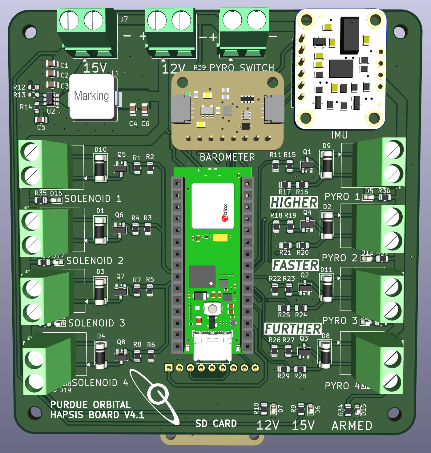
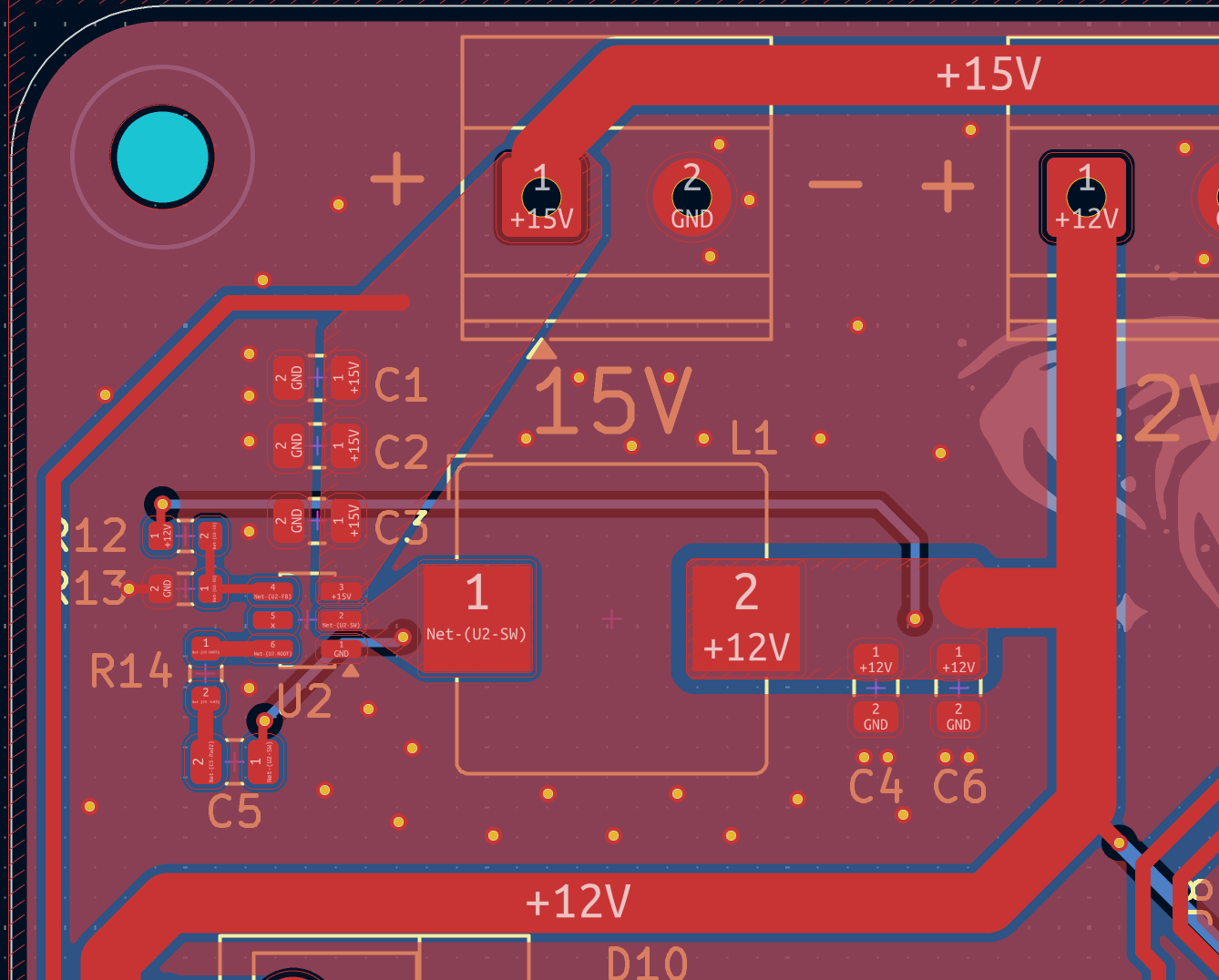
The PCB design was completed in KiCAD, using a two-layer stackup. Ground planes were used on both layers, and stitched together with vias. The heart of the design is the ESP32 microcontroller, which interfaces via I2C with the IMU and barometer. Data is logged to a microSD card via SPI.
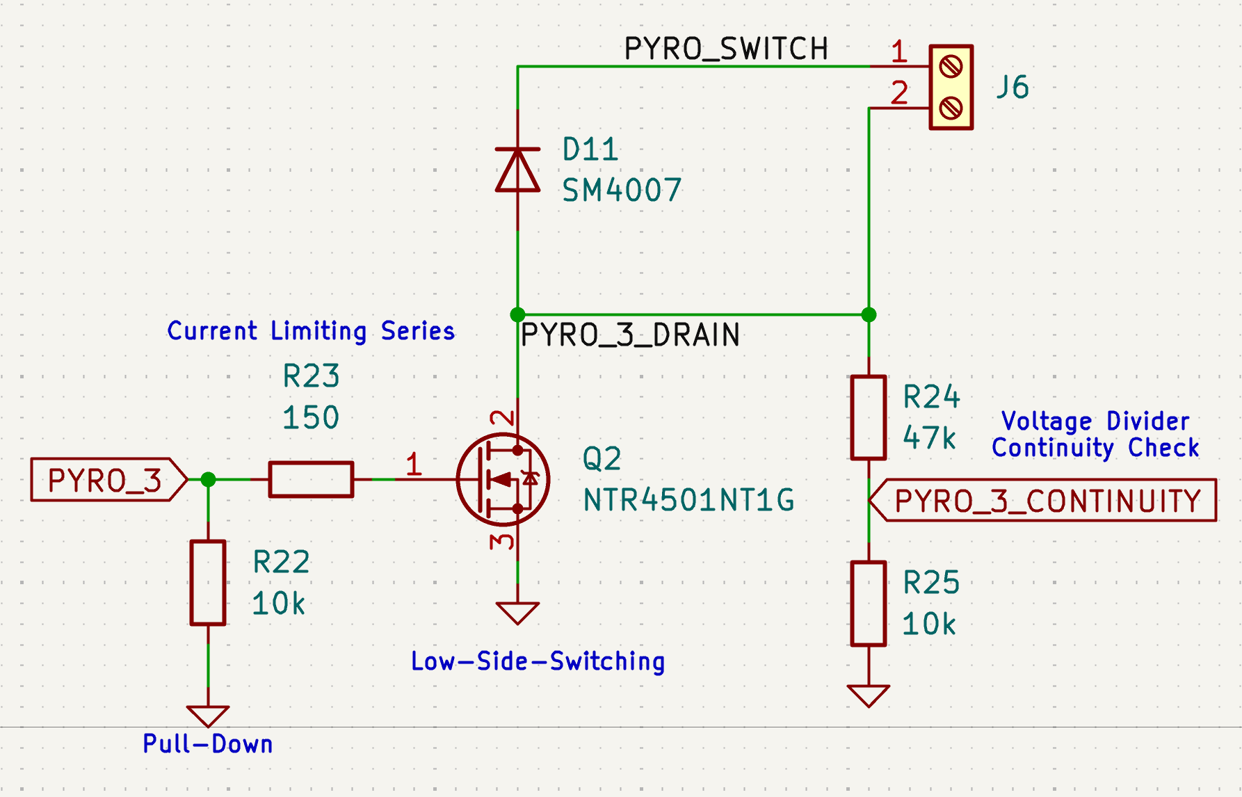
One of the big challenges was designing the pyro channels in a safe and reliable way. There are four pyro channels, each with a low-side MOSFET for activation, and they're pulled down to ground with resistors. To monitor if the pyro is connected, a voltage divider is used to check for continuity.
Another challenge was desinging a buck converter that would step a 14.8V 4S LiPo down to 12V to power the MCU and solenoids. Desining around a peak output current of 2A, I select the TPS56339 which ended up working great. The design was simulated using the TI Webench tool, which is super powerful and lets you optimize the design for different parameters. A nice feature of this IC is that the duty cycle can go up to 97%, meaning that the output will stay stable even as the battery voltage drops to near 12V.
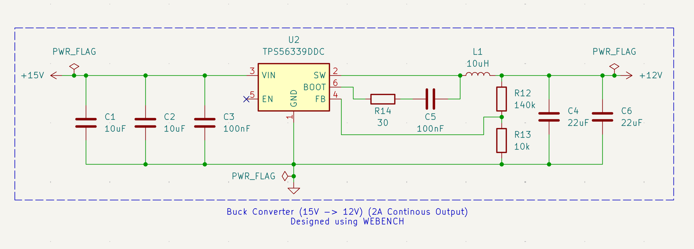
Laying out the buck converter was a bit tricky, but I followed the datasheet recommendations and it ended up working out great. I think using wide copper pours for the high-current paths, and keeping everything compact really helped with noise and stability. I also made sure to include plenty of vias to deal with heat and try to reduce the loop area.
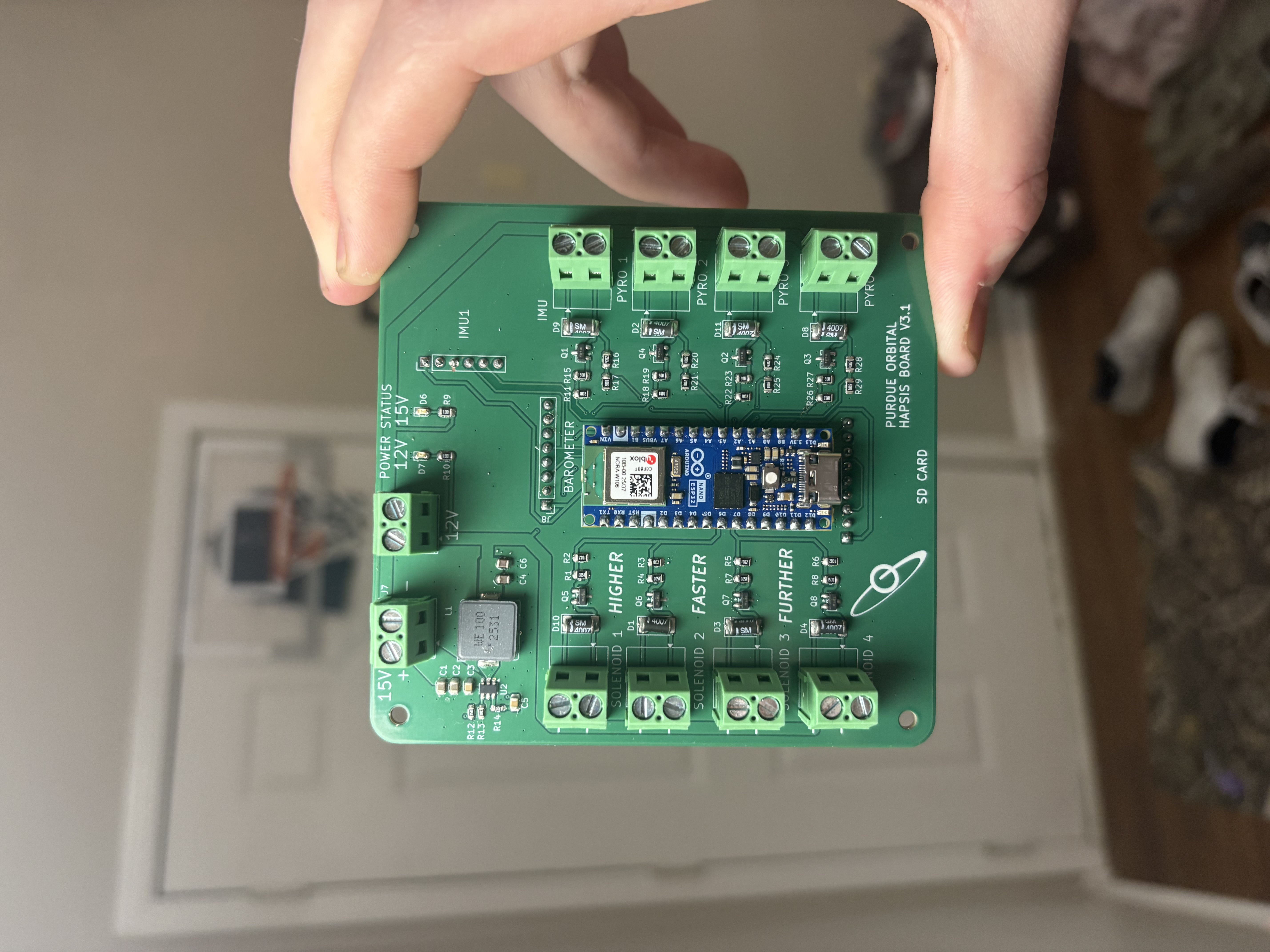
After ordering the boards, I assembled them using soldering paste and a lot of patience. I didn't have a reflow oven or hot air plate, so I ended used using my stove with a pan and a block of aluminum as a makeshift hot plate. Using a therometer to keep track of the temp, I was able to match the manufacturers reflow profile pretty closely. This method worked great for me.
Before we had this fancy PCB, we did all our testing on a perfboard with quesionable wiring. This worked great for quick iterations and software development, but having a custom PCB is a game changer. Here's a graph of some of our early testing data. We spun the system up by hand and observed the response.

  unsigned long currentTime = millis();

  // Consistent 100Hz loop for state management and control
  // Non-blocking
  if (currentTime >= lastLoopTime + LOOP_PERIOD) {
    unsigned long deltaMs = currentTime - lastLoopTime;
    lastLoopTime = currentTime;
    float deltaT = deltaMs / 1000.0;

    // Read sensor data
    float temperature, pressure, altitude;
    float roll, pitch, heading, vertical_accel;
    readBarometer(temperature, pressure, altitude);
    readIMU(roll, pitch, heading, vertical_accel);

    // Log data
    if (currentTime >= lastLogTime + LOG_PERIOD) {
      logData(currentTime, temperature, pressure,
         altitude, roll, pitch, heading, vertical_accel,
          leftThrusterOn, rightThrusterOn, currentState);
      lastLogTime = currentTime;
    }
The code above shows the main control loop, using non-blocking timing to keep track of state, log data, and calculate control outputs. All of these parameters are tunable in a config file, which makes adjusting the system easy and safe.
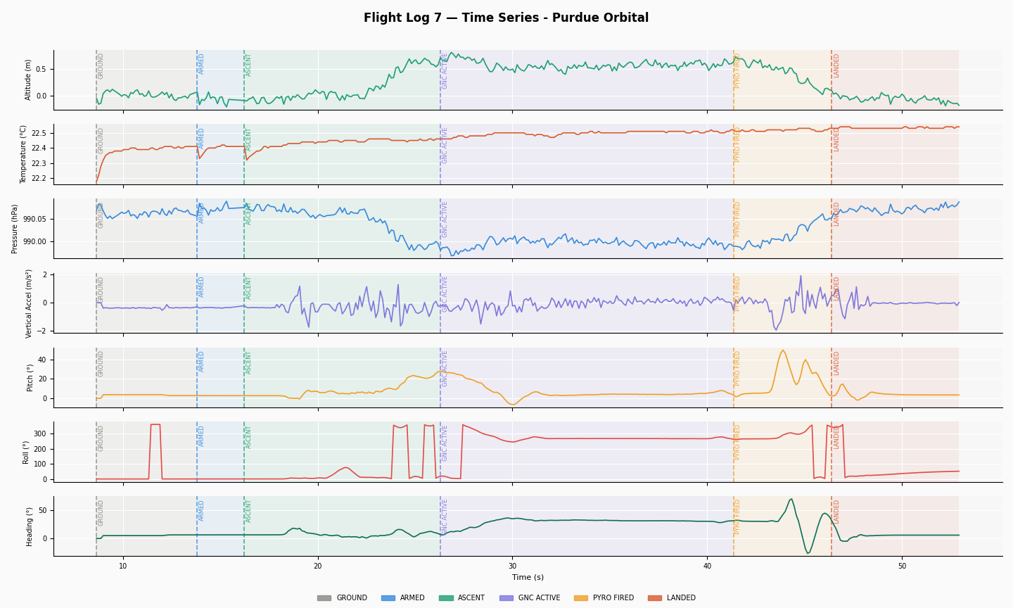
With the new PCB, we were able to record lots more data, such as altitude, pressure, roll, pitch, yaw, acceleration, and more. The data recorded from a bench test is shown below.